Quick Start Guide
Required hardware
- PhotonDrive PDB 500 HotSwap
- PhotonDrive ESC-R-150 or another compatible ESC
- Flight controller
- BLDC motor
- 6S–13S LiPo battery; use 8S or higher if the 15 V output is required
- Power leads and connectors sized for each input and output current
- Signal wire
Before connecting power
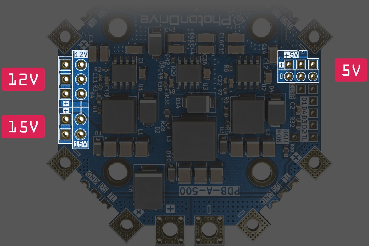
Use a 6S–13S LiPo battery and keep the input within 21.0–54.6 V. The 5 V and 12 V outputs support that range; the 15 V output requires 8S–13S. All connected ESCs and auxiliary loads must suit the selected supply.
Use battery power. A bench supply, smoke stopper or current limiter that folds back or collapses the PDB input to 0 V is unsuitable. A 14S LiPo also exceeds the supported input range.
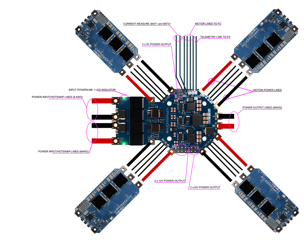
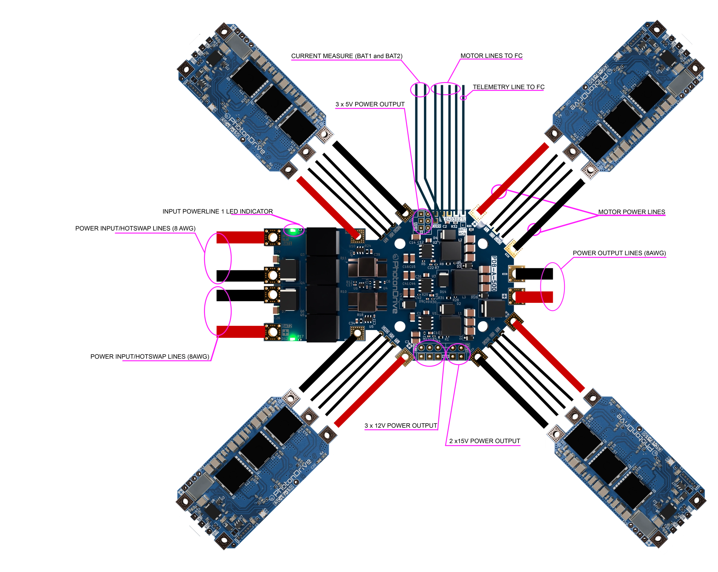
Wiring diagram
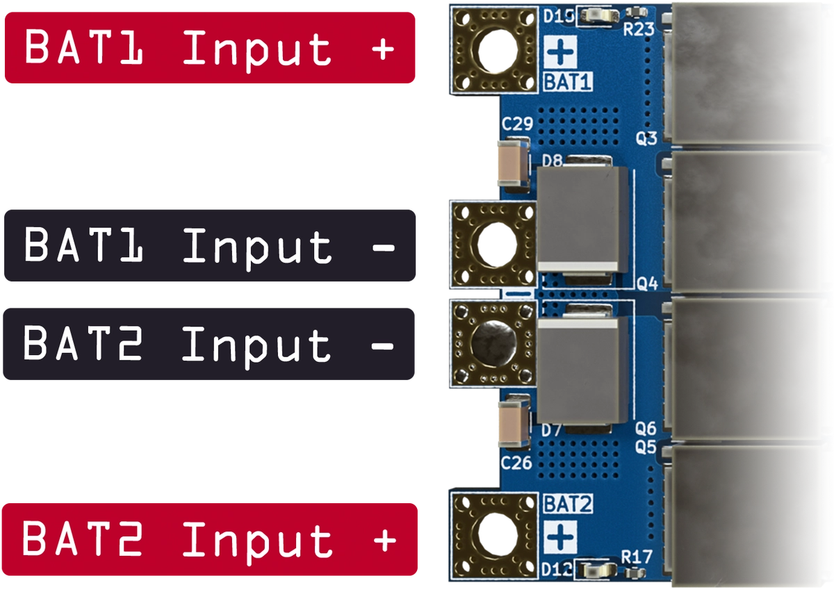
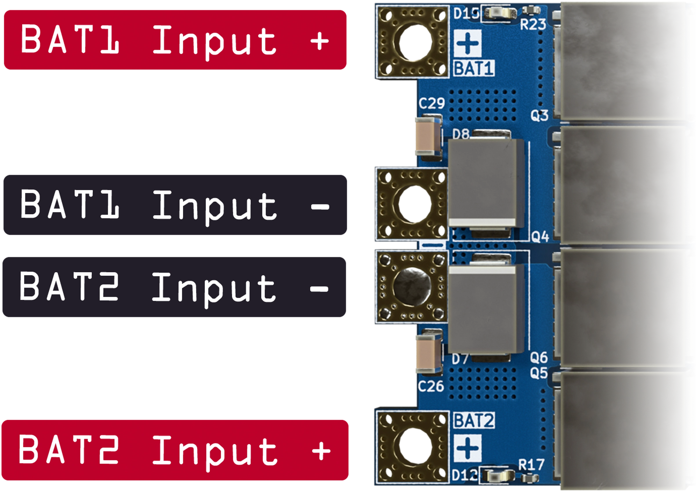
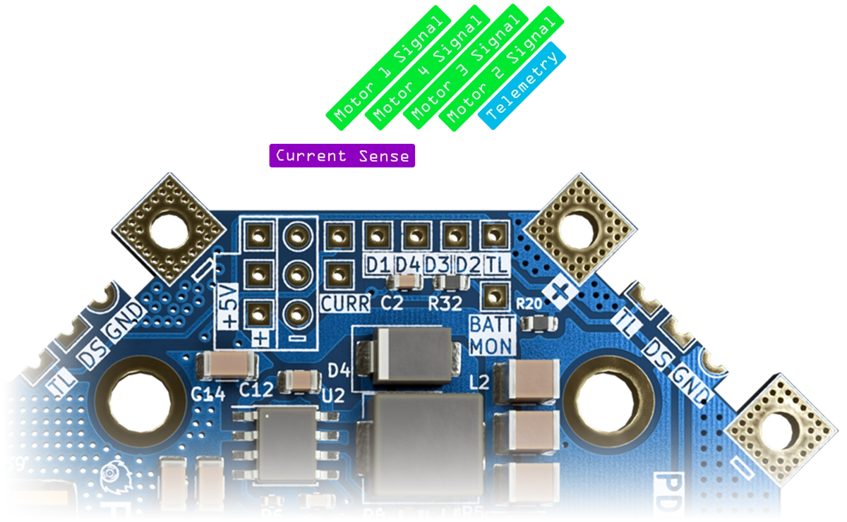
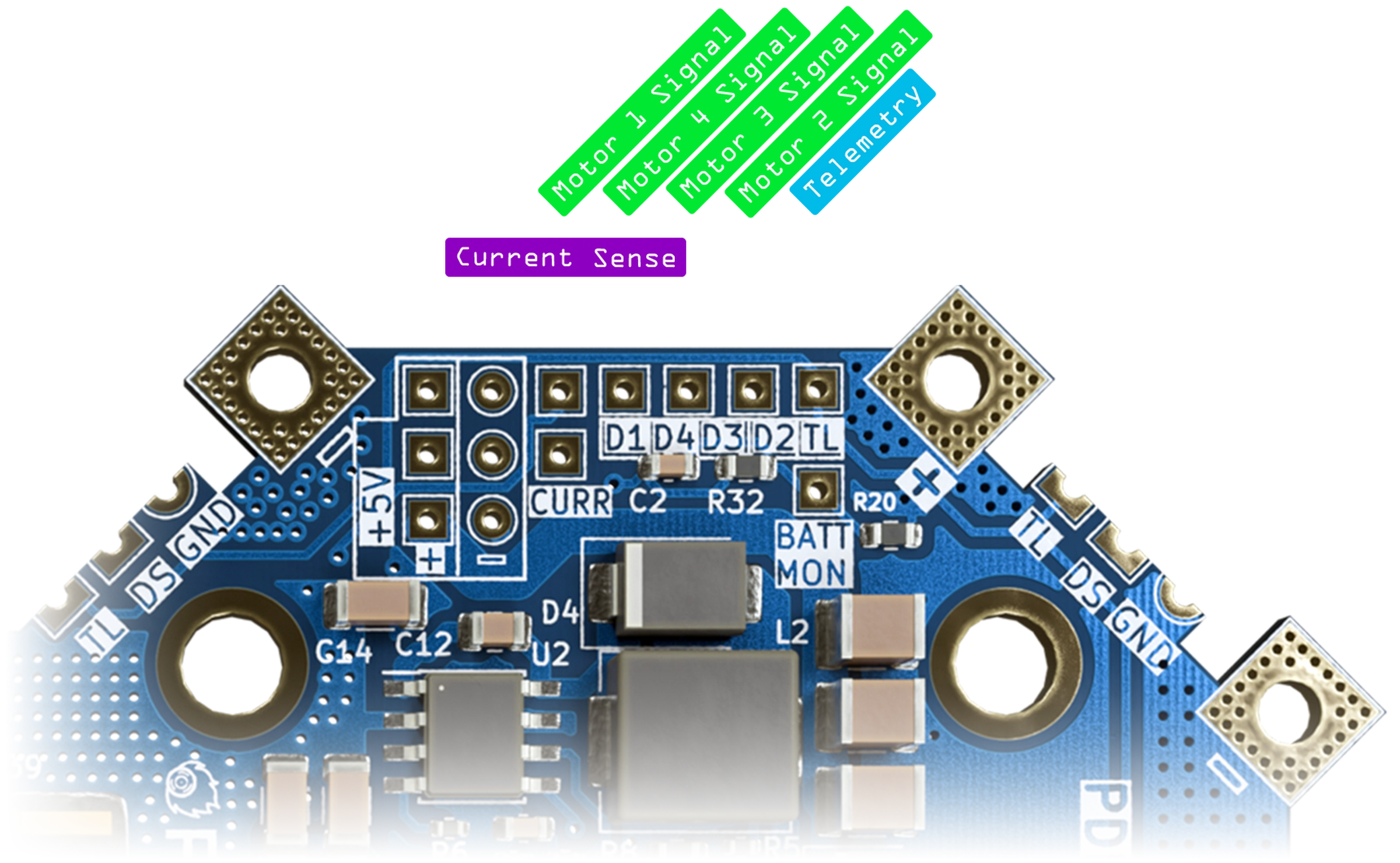
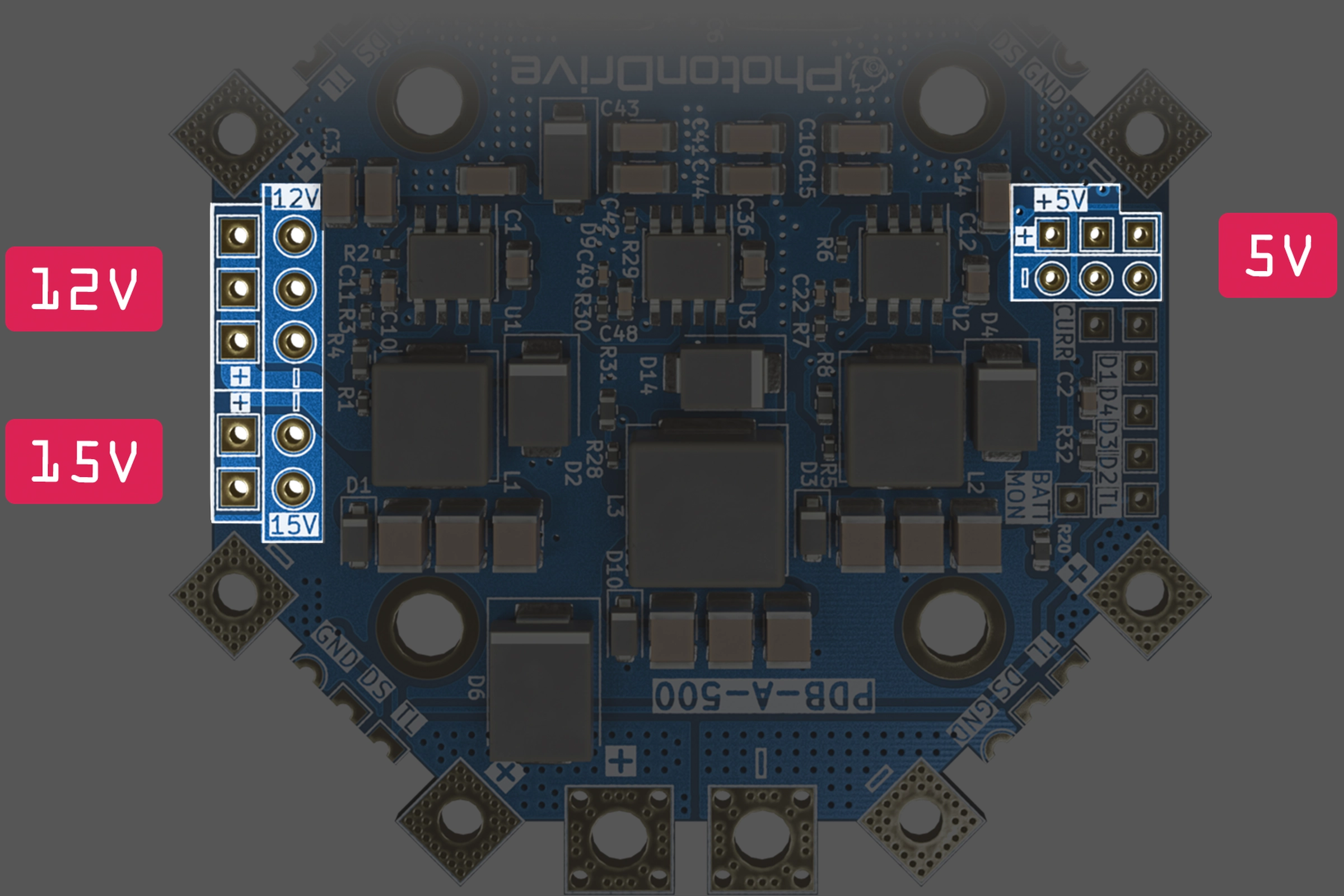
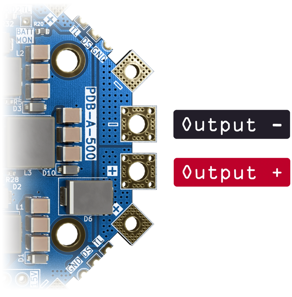
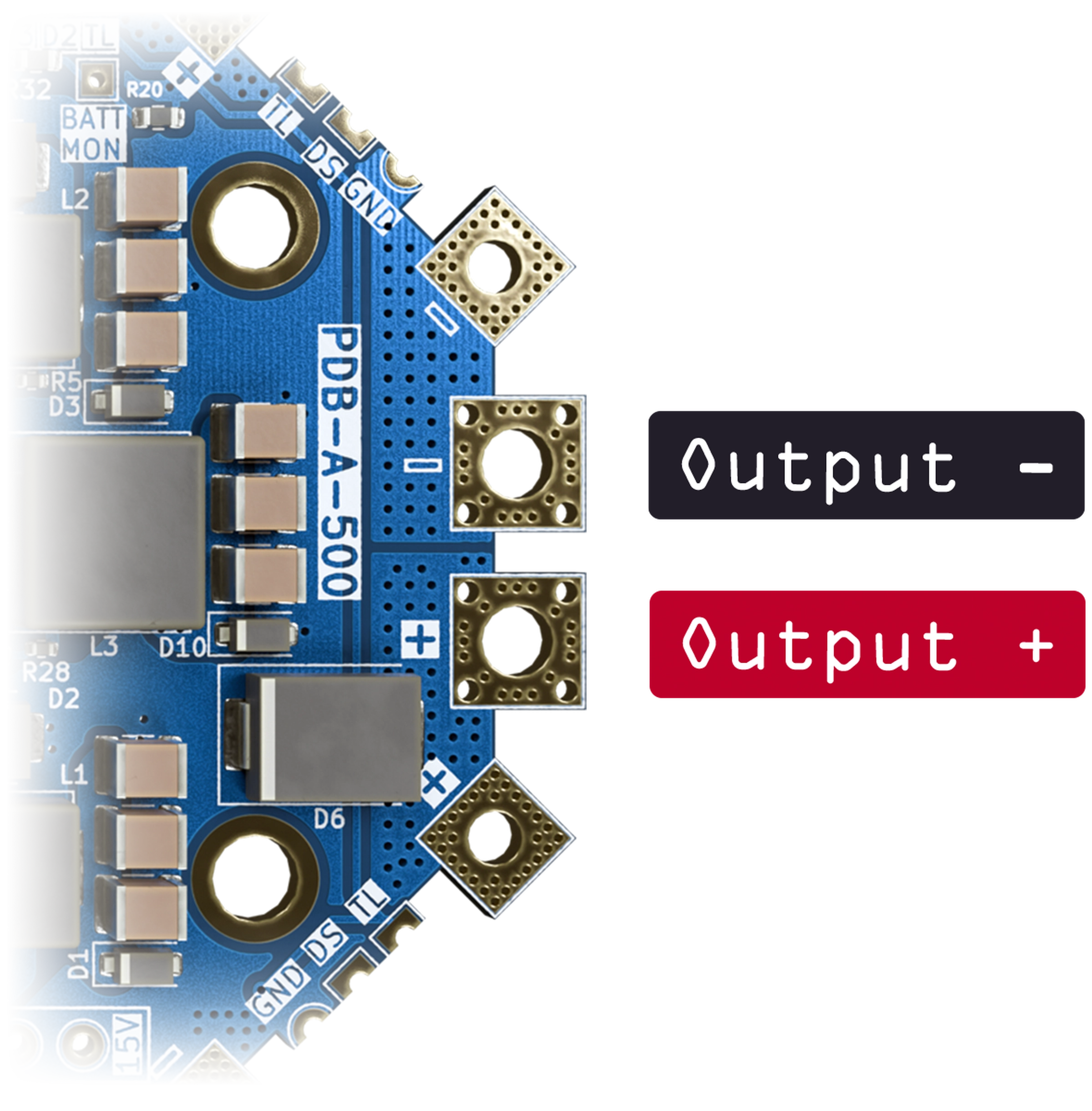
Confirm every connection against the diagrams below. The PDB 500 HotSwap can be used with the PhotonDrive ESC-R-150 or another ESC that meets the same voltage and current requirements.
Soldering the power leads
The input and output pads are backed by eight layers of heavy copper, so they draw heat away quickly. Given enough energy they wet cleanly; starved of it, a joint can look finished without being sound.
- Preheat the board rather than driving all the energy through the tip.
- Use a chisel tip with real thermal mass and keep the contact time short.
- Provide strain relief on every lead. These are heavy conductors on a board built for 500 A.
- Check that each joint is fully wetted, and check the surrounding copper for bridges, before applying power.
Joint resistance dissipates power as the square of current. With a single battery connected, one input carries the whole load, so terminations on the input pads deserve particular care.
First power-up
- Disconnect the ESCs and auxiliary loads.
- Check battery polarity and measure for a short circuit across each input.
- Remove all propellers, secure the motors, fit an appropriately rated fuse and connect one supported battery.
- Verify the main output and every regulated rail used by the installation. The 15 V rail requires an 8S–13S battery.
- Add one load at a time, checking polarity before every connection.
This one-battery procedure is for checking the installation. Each regulated output’s 3 A rating is shared across its connection pads.
Replacing a battery
Either battery can be replaced while the other keeps the system powered.
- Reduce the system load to a level verified for one battery input and its wiring, connectors and cooling. The 500 A rating is the combined figure for both inputs sharing the load; no single-input current rating is specified.
- Confirm that the battery which will remain connected can support that load.
- Disconnect and replace one battery only, checking polarity and compatibility before connecting the replacement.
- Confirm stable system voltage and both input connections before increasing the load. Do not disconnect both batteries if power must be maintained.
Need help with your setup? Contact us.